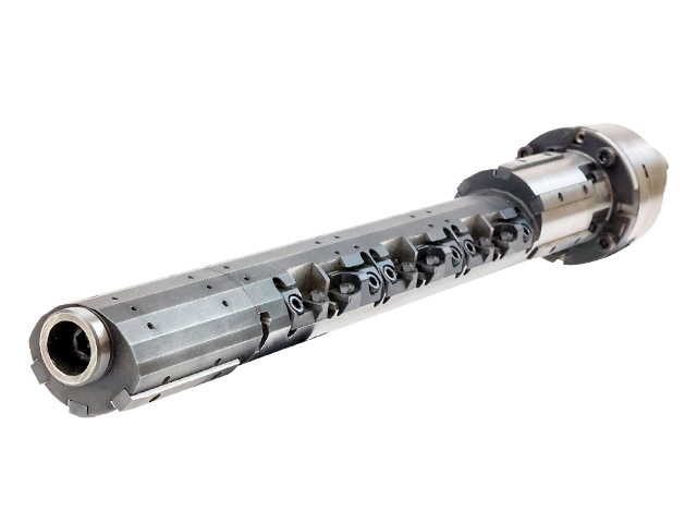
Crescent Line BarPAT.P
No dedicated machine required! No special jig required!
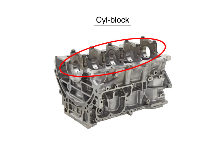
Revolutionary method for crank hole finishing
- A single machining center enables multi-product mixed production: low capital investment.
- 60% reduction of capital investment by applying machining center
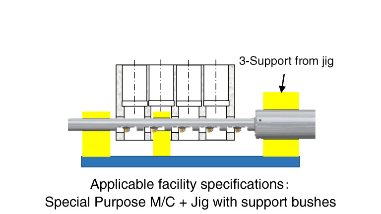
- Application of simple jig configuration
- Applicable to multi-product mixed flow production
“Amazing Ideas / Facts!”
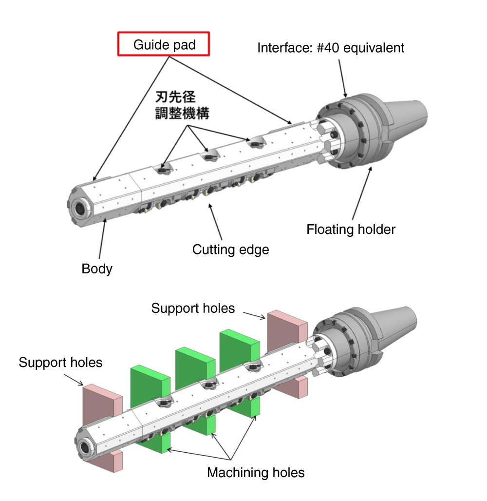
- Configuration:
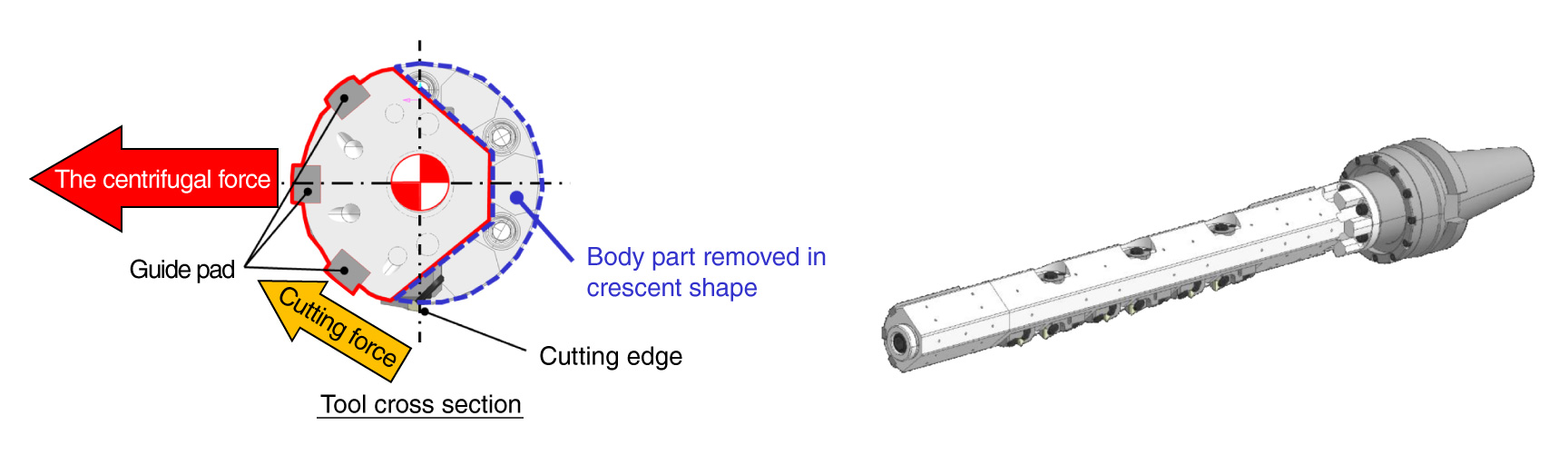
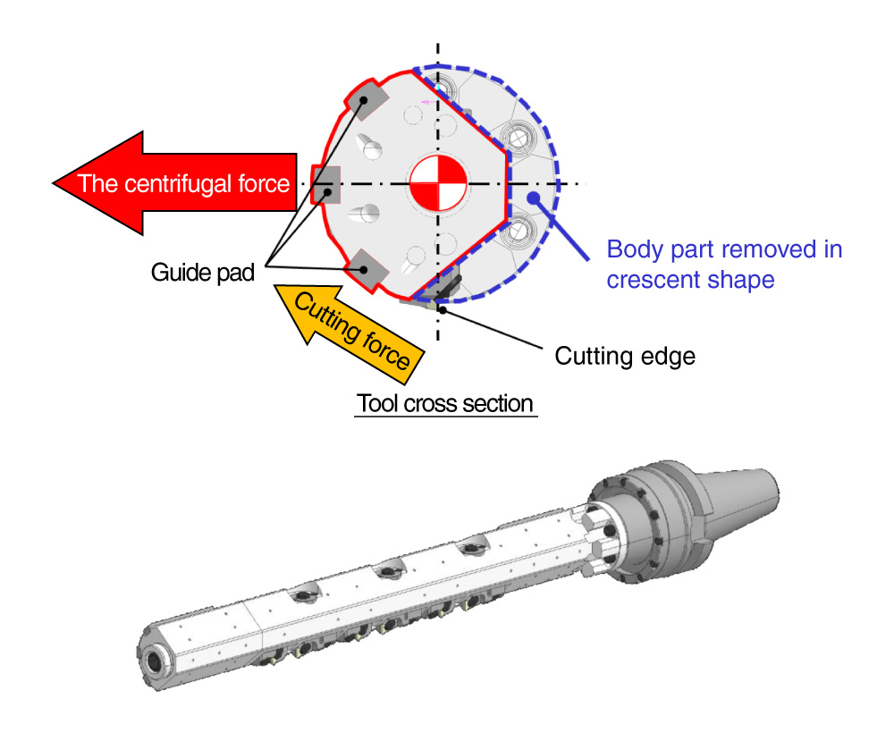
- Unbalanced body shape and special guide pad phase arrangement
- Function:
- Controls the contact surface pressure of the guide pad by centrifugal force generated during rotation.
- Advantage:
- reduction of investment and multi-product mixed production
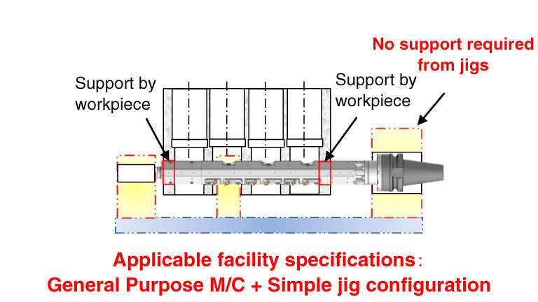
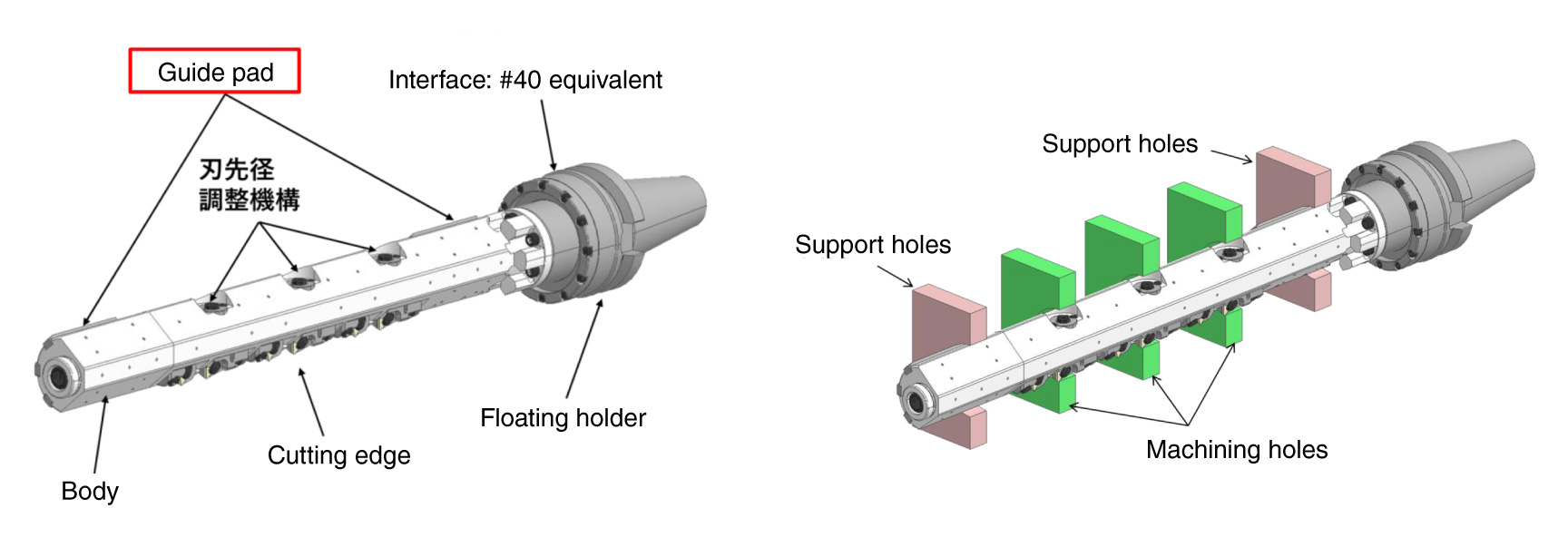
** By using both ends of the crank hole as a guide hole, no support bush is required and machining center processing is possible.
Simple jig configuration results in investment reductionGood !
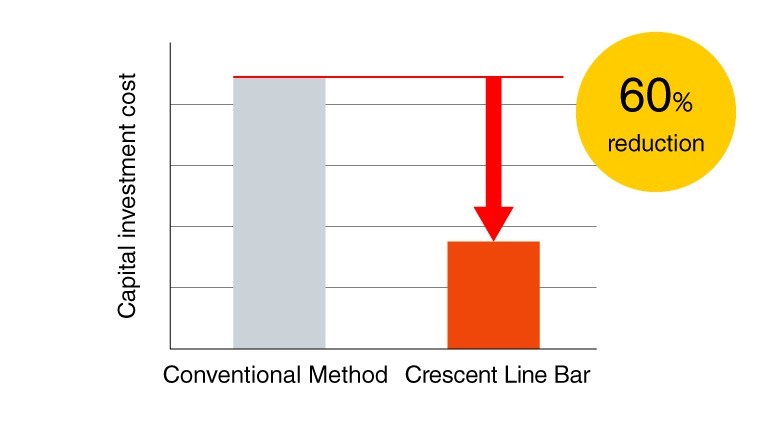
Conventional Method
Crescent Line Bar
POINT!
Unbalanced body shape and special guide pad phase arrangementExcellent !
The centrifugal force and the cutting force keep the guide pad press to the support hole, matching the support hole center to the tool center.
POINT!
Supported by holes on both ends of the workpiece and guide padsExcellent !
POINT!
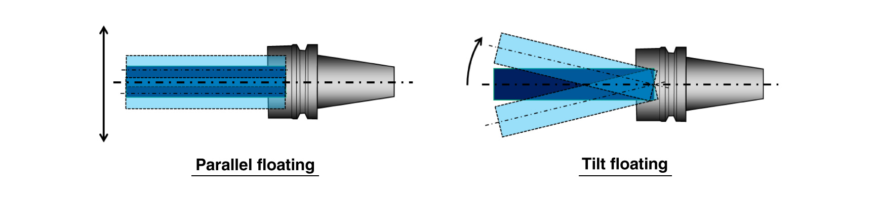
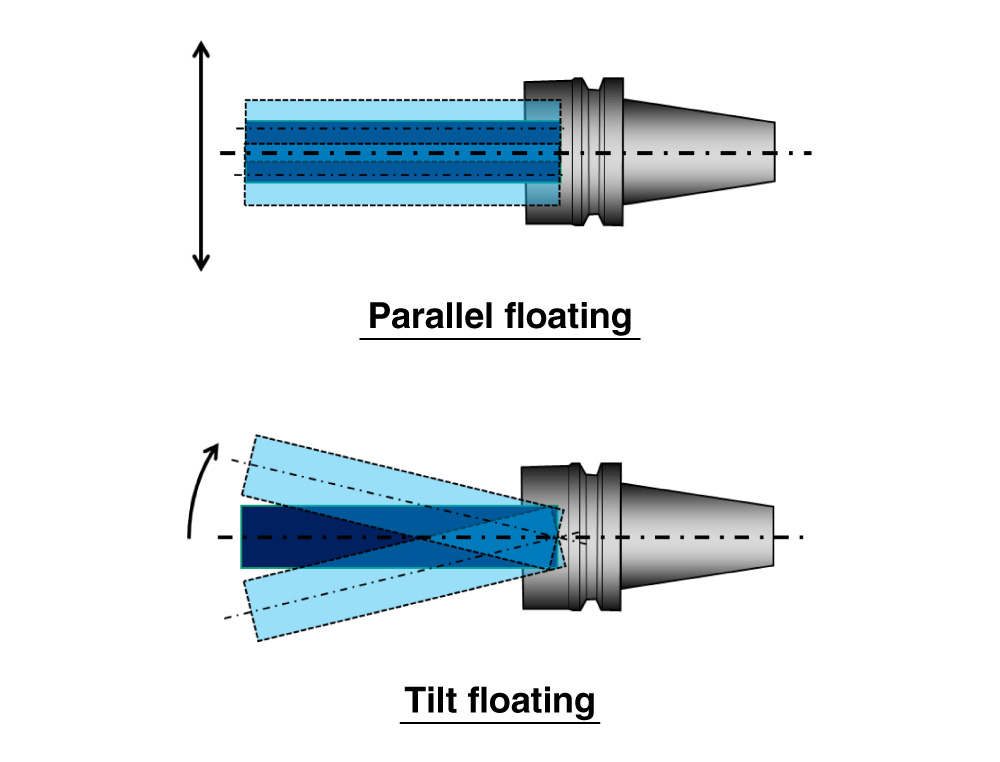
The floating functionExcellent !
For both parallel and tilted directions
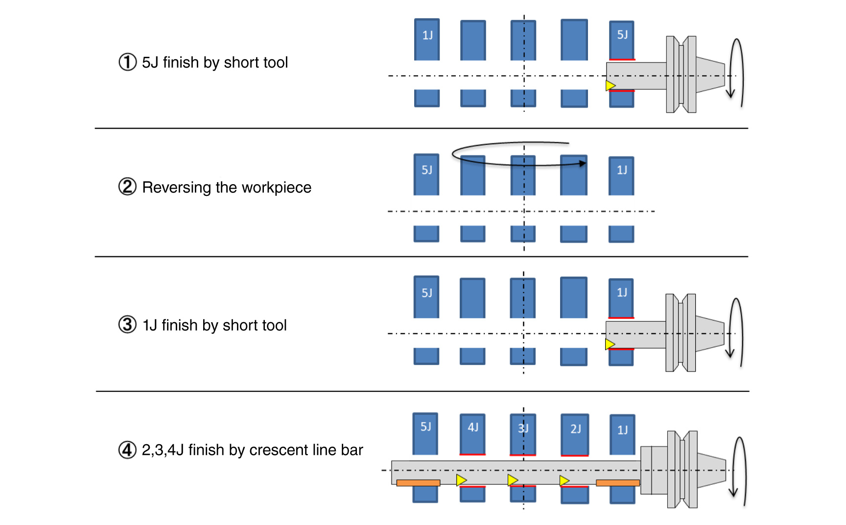
Machining cycle
Background / Point for Development
Background
- For crank holes in cylinder blocks, high accuracy of coaxiality is required with the use of special equipment, jigs, and long line bars, which require a large amount of capital investment and multi product production is made difficult.
Point for Development
- The crescent line bar achieves the same accuracy as in the dedicated M/C with machining center processing by using the holes at both ends of the workpiece as guide holes.
- The product name comes from the crescent (Unbalanced)-shaped part of the body that was removed.
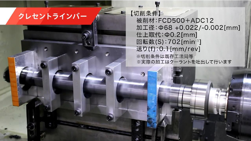
Example
| Used machine | HSK63 horizontal machining center |
|---|---|
| Workpiece | Cyl-Block ass'y simulated workpiece |
| Material | FCD500+ADC12 |
| Tool Diameter | ø68mm +0.022/-0.002 |
| Cutting Conditions |
|
| AP | ø0.2 |
| Coolant | Internal |
| Coaxiality | 7µm |
| Roundness | 5µm |
Product Specification
Tool Specification
| Process covered |
Cyl-block clank hole finish*1) |
|---|---|
| Diameter | ø65 - |
| Standard conditions |
|
| Coaxiality | 10µm以内 |
- *1)A separate tool is required to finish the journal on both ends.
- *2)The max. rotation speed varies depending on the workpiece machining diameter and tool length.
Applicable workpiece example